Introduction to Creating a 3D Model Drawing in the Mold Base Industry
Creating a 3D model drawing in the mold base industry is a crucial step in the manufacturing process. It allows designers and engineers to visualize and analyze the components of a mold base before production. In this article, we will provide step-by-step instructions on how to create a 3D model drawing for a mold base.
Step 1: Gather Design Specifications
Before starting the 3D model drawing, it is important to gather all the necessary design specifications. This includes the desired dimensions, tolerances, material requirements, and any other special design considerations. Having a clear understanding of the requirements will ensure an accurate representation of the mold base.
Step 2: Choose the Appropriate CAD Software
Selecting the right Computer-Aided Design (CAD) software is crucial in creating a 3D model drawing. There are various CAD software options available in the market, such as SOLIDWORKS, AutoCAD, and CATIA. Choose a software that is widely used in the mold base industry and suits your specific requirements.
Step 3: Create a New Design File
Launch the CAD software and create a new design file for the mold base. Set the appropriate units and drawing standards based on your project requirements. This will ensure consistency and accuracy throughout the 3D model drawing.
Step 4: Design the Mold Base Components
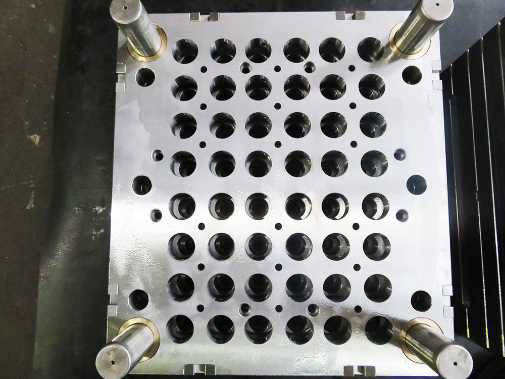
Start designing the individual components of the mold base. This typically includes the cavity plate, core plate, guide pins, ejector pins, sprue bushing, and other necessary components. Use the CAD software's modeling features to create the desired shapes and sizes of each component, taking into account the design specifications.
Step 5: Incorporate Design Changes
Design changes are often required during the mold base development process. The CAD software allows designers to easily incorporate these changes. Make use of the software's editing tools to modify dimensions, add or remove features, or make any necessary adjustments based on feedback or design improvements.
Step 6: Integrate Cooling System
An efficient cooling system is crucial in mold base design to ensure proper heat dissipation during the molding process. Incorporate cooling channels or water lines into the mold base design. Utilize the CAD software's features to create these channels, considering the appropriate diameter, placement, and connectivity.
Step 7: Add Mounting and Alignment Features
To ensure proper alignment and easy installation of the mold base, add mounting and alignment features. This typically includes locating rings, dowel holes, and clamping slots. Carefully design and position these features using the CAD software to ensure accurate alignment and ease of assembly.
Step 8: Validate and Analyze the Model
Once the 3D model drawing is complete, it is essential to validate and analyze the model for potential issues. Utilize the CAD software's built-in analysis tools to check for interference, collisions, and other design flaws. This step helps identify and resolve any problems before proceeding to the manufacturing phase.
Step 9: Generate Technical Drawings and Documentation
After the model is validated, generate the technical drawings and necessary documentation for the mold base. Include all the dimensions, tolerances, and notes required for manufacturing. The CAD software allows the easy creation of detailed and professional drawings, ensuring clear communication between designers and manufacturers.
Conclusion
Creating a 3D model drawing for a mold base is a critical step in the mold base industry. By following the step-by-step instructions outlined above, designers and engineers can efficiently and accurately create a 3D model drawing that meets all the necessary design requirements. This ensures a smooth manufacturing process and a high-quality mold base for the production of various plastic products.


